The PIC32 MCU is a family of 32-bit Microcontrollers designed for best-in-class 32-bit performance and accompanied by a vast offering of software. Since its introduction in 2007, the PIC32 family has established itself as a performance leader stemming from the highest DMIPs/MHz rated MIPS? M4K? core, highly efficient internal bus architecture, and advanced instruction caching. The 5 families of PIC32 MCUs offer a range of general purpose and integrated connectivity peripherals including Ethernet, CAN, and USB host/device/On-The-Go. Integrated flash memory ranges from 32K to 512K and on-board RAM ranges from 8k to 128k.
The PIC32 family is supported by Microchips MPLAB? development environment and well-known industry tools and software providers. Microchip customers benefit from the extensive offering of free software libraries, commonly available in source code form, such as graphics, TCP/IP, USB, encryption, file systems, and digital signal processing software. Most software stacks are compatible across numerous Microchip microcontroller and digital signal processor families. The MPLAB development environment spans the entire Microchip portfolio of over 600 Microcontrollers thus enabling you to use a single tool chain from the lowest cost 8-bit MCU to the highest performing and largest memory PIC32 MCU.
This document describes how to use the PIC32 (General Purpose) Starter Kit, PIC32 USB Starter Kit II, and the PIC32 Ethernet Starter Kit (all also referred to as “starter kit”)as a development tool to emulate and debug firmware on a target board.
1. PIC32 (通用) 入门套件
The PIC32 Starter Kit contains the following items:
? PIC32 Starter Kit Board
? USB Mini-B cable
? PIC32 Starter Kit Installation CD-ROM
The board includes these key features, as indicated in the diagram:
1. PIC32MX360F512L 32-bit microcontroller.
2. Green power indicator LED.
3. Regulated +3.3V power supply for powering the starter kit board via USB or expansion board.
4. On-board crystal for precision microcontroller clocking (8 MHz).
5. USB connectivity for on-board debugger communications.
6. PIC18LF4550 USB microcontroller for on-board debugging.
7. Orange Debug indicator LED.
8. Three push-button switches for user-defined inputs.
9. Three user-defined indicator LEDs.
10. Connector for connecting various expansion boards (on the underside of board).
2. PIC32 USB入门套件II
The PIC32 USB Starter Kit II contains the following items:
? PIC32 USB Starter Kit II Development Board
? USB Mini-B to full-sized A cable – USB debug cable to debug and power the board
? USB Micro-B to full-sized A cable – PIC32 USB cable to communicate with the PIC32 USB port
3. PIC32 以太网入门套件
The PIC32 Ethernet Starter Kit contains the following items:
? PIC32 Ethernet Starter Kit development board
? USB Mini-B to full-sized A cable – USB debug cable to debug and power the board
? USB Micro-B to full-sized A cable – PIC32 USB cable to communicate with the PIC32 USB port
? RJ-45 CAT5 Ethernet patch cable – Ethernet CAT5 cable to communicate with the PIC32 Ethernet port
[page_break]
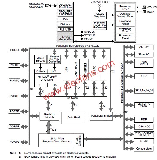
图3.PIC32 (通用) 入门套件开发板方框图
图4.PIC32 (通用) 入门套件电路图(1): PIC32MX CPU
图5.PIC32 (通用) 入门套件电路图(2): PIC18LF4550 DEBUG CPU
图6.PIC32 (通用) 入门套件电路图(3):应用板连接器
图7.PIC32 (通用) 入门套件电路图(4):开关和LED
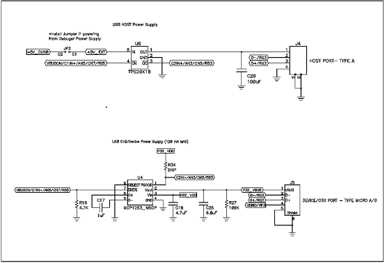
图8.PIC32 (通用) 入门套件电路图(5):电源
PIC32 STARTER KIT SCHEMATIC, SHEET 6 OF 6 (POWER SUPPLY)